
A Sound Diversion
The Atari Pole Position schematics reveal a discrete-chip implementation of what MAME calls a Namco sound device subsystem. This article is primarily concerned with the circuits found on 8th print sheets 6B through 7B.
Master Timing
All the timing associated with the Namco sound is based on the signals developed by the Namco 07xx. From that analysis we know that the horizontal position of the CRT beam scans 384 pixels per line (of which 0..255 are displayed). We used HPOS[8:0] to represent the horizontal position; it operates modulo-384.
Inner Loop Sequencer
The Namco sound subsystem implements a sequencer that advances every pixel, and proceeds through 16 steps before repeating. Therefore, the sequence forms an inner loop that runs at a rate of 384 kHz.
The sequencer performs reads and writes within a 64-byte region of RAM shared by the Z80 CPU. The first fifteen steps perform math on the values in memory, and set up the storage of intermediate values for application to the sound output at the final step of the sequence.
| HPOS[3:0] | Sequencer Action                          |
| --------- | ----------------------------------------- |
| 0         | NOP                                       |
| 1         | NOP                                       |
| 2         | clear carry, fetch byte at base+0         |
| 3         | add byte at base+32 and write-back        |
| 4         | NOP                                       |
| 5         | NOP                                       |
| 6         | fetch byte at base+1                      |
| 7         | add byte at base+33 and write-back        |
| 8         | NOP                                       |
| 9         | NOP                                       |
| 10        | fetch byte at base+2                      |
| 11        | add byte at base+34 and write-back        |
| 12        | NOP                                       |
| 13        | NOP                                       |
| 14        | fetch byte at base+3                      |
| 15        | read byte at base+35, update sound output |
The steps marked NOP are periods dedicated for the Z80 CPU, where the sequencer ensures free slots for the CPU to access the shared RAM.
The result of the sequence through step 11 is to update the 24-bit little-endian value based at RAM offset 32 by adding the 24-bit little-endian value based at RAM offset 0. This is the instantaneous sample/phase position of a waveform generator for the "voice". The PROM at 11H contains 32 4-bit samples for each of eight available waveforms. Only bits 19:15 of the position apply. Since its upper bits are ignored, the position might be better called a 20-bit little-endian value, of which the five MSBs select the sample position.
Outer Loop
The sequencer operates on eight discrete bytes within the sound RAM, four bytes at offset zero and four bytes at offset 32. The three bits HPOS[6:4] form a part of the RAM address at A[4:2]. This amounts to an offset for the sequencer base. The result is that the sequencer inner loop advances its base offset by four bytes at the end of each 16-cycle sequence, and performs its operation eight times before wrapping around to base offset zero.
The MAME sources call this an "eight voice" configuration of the Namco sound device.
Waveforms
The PROM at 11H contains 256 4-bit nibbles. The five LSBs of the address are determined by the phase position of a given voice, and the three MSBs select the voice's active waveform. The eight available waveforms are plotted below.
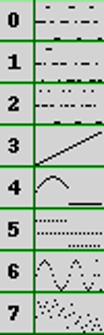
The three waveform selection bits are developed at sequencer step 15, from RAM base+35[2:0].
Making Gains
Pole Position has four separate loudspeaker locations, and each of these is driven by a discrete audio amplifier chain. Sheet 10A reveals that each audio chain gets equal amounts of ENGSND (engine sound is a topic for a future post). However, each chain gets a unique rapidly-updating programmable volume applied to all non-engine sound effects, including those sounds developed here under the Namco sound device.
The programmable volume for each of the four audio chains is expressed as a 4-bit gain. Switched resistor networks are used to implement the analog application of the gain.
The instantaneous digital gain level applied to each chain is determined by the Namco sequencer up to step 14. At step 15, the gains are applied at the same time the Namco audio sample is updated. The gain values are developed as:
- GAIN1 is RAM base+35[7:4]
- GAIN2 is RAM base+2[7:4]
- GAIN3 is RAM base+3[7:4]
- GAIN4 is RAM base+3[3:0]
Note that GAIN2 is actually the (ignored) 4 MSBs of the 24-bit little-endian position increment value for the voice waveform.
Sound Overload
Each of the eight Namco sound device voices may bypass the waveform generator and select an external sound source. In this case the PROM-based waveform samples are ignored, but the quadraphonic GAIN values still apply.
The internal or external audio source determination is also made at sequencer step 15. When the bit at RAM base+35[3] is 0, the PROM-based waveform is selected. When that bit is 1, then the two LSBs, RAM base+35[1:0], select which external audio channel is used. The schematic labels these external signals CHANL[1:4].
Digital-To-Analog
The Namco sound device delivers audio updates to its four audio chains at 384 kHz for eight voices/sources. Each voice/source is therefore updated at 48 kHz with variable gain to all audio chains.
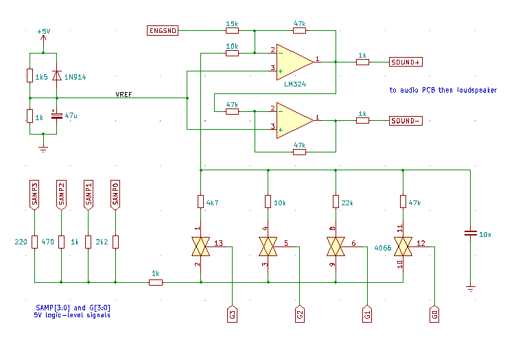
Below is a circuit representing a single audio GAIN chain. The SAMP[3:0] and resistor network is common for to all four chains, the analog switches and downstream op-amps are repeated for each. Each of the analog paths have a 10nF capacitor at the output, forming a simple zero-order hold function for the analog reconstruction of the desired audio.
The MAME developers call the 20-bit value based at RAM base+0 the voice "frequency". It would be more accurate to call this value the 5Q15 (5 integer bits, 15 fractional bits) position/phase increment applied at 48 kHz. The frequency is of course inversely related to this increment value.
A virtual VREF of ~2.0v is found at op-amp side of the 10k resistor. This allows a straigtforward determination of the steady-state voltage at the channel capacitor for each combination of SAMP[3:0] and G[3:0] bits.
Steady-state voltage at 10k input, cV:
GAIN SAMP:   0   1   2   3   4   5   6   7   8   9   A   B   C   D   E   F
  0        200 200 200 200 200 200 200 200 200 200 200 200 200 200 200 200
  1        235 230 224 219 212 207 201 197 186 182 176 171 164 159 153 149
  2        261 252 242 234 221 213 203 194 176 168 158 149 137 128 118 110
  3        277 267 254 243 227 216 204 193 170 160 147 136 120 109  97  86
  4        296 283 267 253 234 221 205 191 163 150 134 121 101  88  72  59
  5        305 290 273 258 237 223 205 191 160 146 128 114  93  78  61  46
  6        313 297 278 263 240 224 206 190 157 142 123 108  85  69  50  35
  7        319 302 283 266 242 226 206 190 155 139 119 103  79  62  43  26
  8        328 311 290 272 246 228 207 189 152 134 113  95  69  51  30  12
  9        332 314 292 274 247 229 207 189 150 132 110  92  65  47  25   7
  A        336 317 295 276 248 230 207 189 149 130 108  89  62  43  21   2
  B        338 319 296 277 249 230 207 188 148 129 106  87  59  40  17   0
  C        342 323 299 280 251 231 208 188 147 127 104  84  55  36  12   0
  D        344 324 301 281 251 232 208 188 146 126 103  83  53  34  10   0
  E        346 326 302 282 252 232 208 188 145 125 101  81  51  31   7   0
  F        348 328 303 283 253 233 208 188 145 124 100  80  50  29   5   0
We note that the op-amps operate in inverting mode, and that a differential full-scale output is developed.
Sample Sounds
A pure-Python implementation of the Namco sound system allows us to "play back" the state of the 64-byte RAM area from various times during game play. Here is a few seconds reproduced from my interpretation of the schematics and some time-tagged RAM writes from MAME.
Coin Up, Start Music, Green Light
Summary
Pole Position implements a Namco sound device using discrete logic chips, with timing derived from the CRT beam position. Eight quadraphonic voices are developed, where each updates at 48 kHz and provides a dynamically-weighted audio source selected from either one of eight programmable-frequency waveforms, or from one of four other sound sources (e.g. voice prompts, explosions, and tire-screeching).